
Gearbox Selection Guide
Gearbox Axial Load Explained: Thrust Loads, Bearings & Selection
Gearbox axial load is a push or pull force acting along the centreline of an input or output shaft. It is different from radial load, which acts across the shaft. Ignoring axial thrust can overload gearbox bearings, create shaft movement, increase seal wear and shorten the operating life of the complete drive. This guide explains axial load, thrust direction, combined shaft loads and the checks required when selecting a gearbox.
Key point: permissible axial load is not a single figure that applies to every gearbox. Capacity can vary with gearbox type, frame size, ratio, shaft design, bearing arrangement, speed, load direction and operating life. Always check the manufacturer’s data for the exact gearbox configuration.
What Is Gearbox Axial Load?
An axial load is a force acting parallel to the centreline of a rotating shaft. It tries to push the shaft into the gearbox or pull it away from the gearbox rather than bend it sideways.
Axial load is also commonly described as:
- Thrust load
- Axial force
- Shaft thrust
- Push or pull force
- Longitudinal shaft load
In technical catalogues, axial force may be represented by symbols such as Fa, FA or FA. The permitted value is normally stated in newtons.
Axial force acts along the shaft centreline
The force may push towards the gearbox or pull away from it, depending on the machine and direction of operation.
Gearbox bearings must locate the shaft while supporting the forces created by the internal gears and the connected machine. When the external axial load is greater than the bearing arrangement can support, bearing life can fall sharply.
Do not confuse axial load with output torque. Torque twists the shaft around its centreline. Axial load pushes or pulls along that centreline. A gearbox can have adequate torque capacity but still be unsuitable for the applied thrust force.
Axial Load vs Radial Load
Gearbox output shafts can experience several different loads at the same time. The three most important are axial load, radial load and bending moment.
Axial load
Acts parallel to the shaft. It pushes the shaft into the gearbox or pulls it out from the gearbox.
Example: thrust from a screw conveyor.
Radial load
Acts at approximately 90 degrees to the shaft centreline and tries to bend the shaft sideways.
Example: belt tension on a pulley.
Bending moment
Results when a radial force acts at a distance from the gearbox bearing support, increasing leverage on the shaft.
Example: an overhung sprocket.
| Load type | Direction | Typical causes | Main components affected |
|---|---|---|---|
| Axial | Along the shaft centreline | Screws, propellers, pumps, helical gearing and vertical loads | Thrust faces, bearings, shoulders and retaining components |
| Radial | Across the shaft | Belts, chains, pulleys, sprockets and external gears | Shaft, bearings and gearbox housing |
| Torque | Rotation around the shaft | Resistance from the driven machine | Gears, keys, splines, shaft and coupling |
Read our separate guide to gearbox radial and overhung loads for a detailed explanation of pulley, sprocket and shaft-extension forces.
Push Loads vs Pull Loads
Axial force can act in either direction. Descriptions vary between manufacturers, but the load is often defined as either pushing towards the gearbox or pulling away from it.
Push load
The connected machine pushes the shaft towards the gearbox housing. This may be described as compressive thrust, inward thrust or a positive axial direction, depending on the manufacturer’s drawing convention.
Pull load
The machine pulls the shaft away from the gearbox. This may be described as tensile thrust, outward thrust or a negative axial direction.
The permitted force may not be identical in both directions. One side of the bearing arrangement may be better supported than the other, and internal gear thrust can either oppose or reinforce the externally applied load.
Always define the force direction using a drawing. Terms such as positive, negative, inward and outward can be interpreted differently. A simple arrow showing the actual force direction prevents selection errors.
Can the thrust direction reverse?
Yes. Reversing the gearbox rotation or changing the process can reverse axial thrust in certain applications. Screw conveyors, augers, mixers and helical gear systems may apply thrust in opposite directions during forward and reverse running.
Where the machine operates in both directions, the gearbox must be checked for the maximum axial force in each direction—not only the normal running direction.
What Causes Gearbox Axial Load?
Axial load can originate inside the gearbox, outside the gearbox or from a combination of both.
Internal gearing
Helical, bevel and worm gear meshes can generate axial components as torque passes through the gear teeth.
Driven-machine thrust
Screws, impellers, fans, propellers, pumps and extrusion equipment can push or pull directly on the output shaft.
Installation error
Incorrect coupling alignment, insufficient shaft clearance or thermal expansion can unintentionally force a shaft into the gearbox.
It is important to separate these sources because the manufacturer’s permissible external axial-load value may already account for the internal forces generated by the gearbox at its rated operating condition.
Do not add or subtract internal gear forces using a general online formula unless the gearbox manufacturer specifically requires it. Catalogue ratings and bearing checks are normally based on the manufacturer’s own geometry, direction conventions and design assumptions.
Internal Gear-Generated Axial Thrust
Some gear-tooth arrangements naturally generate thrust as torque passes through the gear mesh. Bearings inside the gearbox are selected and positioned to control these forces.
Helical gearboxes
The angled teeth of a helical gear create smooth engagement and high contact overlap. However, the helix angle also creates an axial component of force that must be reacted by the bearings.
Helical bevel gearboxes
Bevel gear geometry changes the direction of power transmission and produces several force components. The bearing arrangement must control radial and axial forces while maintaining the correct gear alignment.
Worm gearboxes
The sliding, screw-like worm engagement creates thrust along the worm shaft. The size and direction of that thrust depend on transmitted torque, geometry and direction of rotation.
Planetary gearboxes
Symmetrical planetary stages can balance some internal forces, but external thrust and forces created by connected components still require checking against the exact unit’s output-bearing rating.
Gearbox manufacturers account for internal gear forces when designing the shaft and bearing arrangement. The user’s responsibility is to provide accurate information about any additional external load applied by the machine.
Browse our ranges of worm gearboxes , inline helical gearboxes and helical bevel gearboxes .
External Axial Loads on the Gearbox Output Shaft
External axial load is the additional thrust transferred from the driven machine into the gearbox output shaft or hollow bore.
Common sources include:
- A screw or auger pushing material through a process
- A pump impeller generating hydraulic thrust
- A propeller moving fluid or air
- A mixer blade producing process reaction forces
- A vertical shaft carrying suspended mass
- A lead screw converting rotation into linear movement
- A coupling installed without adequate axial movement
- Thermal expansion of a long machine shaft
- Misalignment between connected components
- A helical pinion or external bevel gear mounted on the output shaft
External thrust may be continuous, intermittent, reversing or created only during starting, blockage or abnormal process conditions. The maximum realistic load—not just the normal steady-state value—must be considered.
Peak load matters: a screw conveyor may operate with moderate thrust during normal flow but produce a much larger force during startup, compaction or a blockage. These short-duration loads can govern gearbox and bearing selection.
How Axial Load Affects Gearbox Bearings
Bearings keep the gearbox shafts in the correct position and maintain accurate gear alignment. When axial load increases, the bearing contact stress and internal load distribution change.
Excessive axial force can contribute to:
- Reduced bearing fatigue life
- Higher bearing temperature
- Increased friction and power loss
- Loss of correct gear-tooth alignment
- Abnormal gear noise
- Excessive shaft end float
- Seal wear or leakage
- Damage to retaining rings, shoulders or end covers
- Premature gearbox failure
Bearing type matters
| Bearing arrangement | General characteristic | Selection consideration |
|---|---|---|
| Deep-groove ball bearing | Can support radial load and a degree of axial load | Permissible thrust depends on bearing size, speed, radial load and internal clearance |
| Angular-contact bearing | Designed to support combined radial and axial loads | Direction and arrangement—single, paired or opposed—are important |
| Taper-roller bearing | Supports combined loads and can provide high stiffness | Preload, orientation and opposing-bearing arrangement affect capacity |
| Thrust bearing | Primarily intended to support axial load | May support one direction or both directions depending on design |
| Spherical-roller thrust bearing | Used for high thrust and some misalignment capability | More common in heavy industrial shaft systems than small standard gearmotors |
The presence of a particular bearing type does not by itself prove that a gearbox can withstand a proposed thrust load. The complete shaft, housing, bearing spacing, lubrication and internal gear forces must all be considered.
What Is Permissible Gearbox Axial Load?
Permissible axial load is the maximum external thrust force approved by the gearbox manufacturer for a defined operating condition.
The catalogue value may depend on:
- Gearbox series and frame size
- Gear ratio
- Output-shaft type
- Solid shaft, hollow shaft or flange output
- Direction of the applied force
- Input or output speed
- Output torque
- Radial load acting at the same time
- Required bearing operating life
- Mounting position
- Duty cycle and operating hours
- Lubrication and ambient conditions
A permissible load in a catalogue is only valid under the conditions stated by the manufacturer. Where the application differs—such as reversing thrust, high speed, continuous operation or simultaneous radial load—a specific engineering check may be required.
Static load vs dynamic load
A static axial load acts while the shaft is stationary or moving very slowly. A dynamic load acts during rotation and influences bearing fatigue life. A bearing may withstand a high static force without permanent damage but still have insufficient life when the same force is applied continuously at speed.
Continuous load vs peak load
Continuous thrust affects heat and bearing fatigue over many operating hours. Peak thrust may occur during startup, stopping, reversal, blockage or process upset. Both values should be supplied when requesting selection support.
Combined Radial and Axial Gearbox Loads
Gearbox bearings frequently support radial and axial forces at the same time. The full permissible value for one direction may not remain available when a substantial force is already acting in the other direction.
For example, an output shaft may carry:
- Radial force from a chain sprocket
- Axial force from a helical drive pinion
- Torque from the driven process
- Shock loading during starts or reversals
Manufacturers may use a combined-load formula, bearing-life calculation, correction factor or application-specific engineering check. The correct method varies between gearbox ranges.
Do not independently approve combined loads by checking each value against its separate maximum. A gearbox rated for a certain radial load and a certain axial load may not be rated to carry both maximum values simultaneously.
Why radial load position matters
A radial force applied near the gearbox housing produces less bending leverage than the same force applied near the end of a long shaft extension. The axial force may be unchanged, but the combined bearing reaction and shaft stress can be much higher.
When requesting a combined-load check, provide the distance from the gearbox mounting face or shaft shoulder to the centreline of the pulley, sprocket or gear.
Why Axial-Load Direction Matters
Direction affects which bearing surfaces carry the load and how the external force interacts with internal gear thrust.
The same numerical force may therefore produce different bearing reactions when:
- The gearbox rotation is reversed
- The output shaft is installed on the opposite side
- The gear hand or helix direction changes
- The shaft is pushed instead of pulled
- The mounting position changes
- The driven process reverses thrust
Supply a clear sketch showing the gearbox, output shaft, direction of rotation and axial-force arrow. This is more reliable than describing the force only as “positive” or “negative”.
Rotation direction and helical elements
With helical screws and gears, reversing rotation can reverse the thrust direction. This can move the load from one side of the bearing arrangement to the other. Bidirectional operation should always be stated during selection.
Applications That Commonly Create Axial Thrust
Screw conveyors
The rotating flight pushes bulk material along the casing. The material reaction can create significant thrust along the screw shaft.
Extruders
Material compression and pressure at the die can create very high continuous thrust. Dedicated thrust-bearing arrangements are often required.
Mixers and agitators
Angled blades can produce axial process forces, especially in viscous fluids or when solids are present.
Pumps
Impellers can generate hydraulic thrust that changes with flow, pressure, operating point and impeller design.
Propellers and fans
Moving air or liquid creates a reaction force along the drive shaft. Reversal can change both magnitude and direction.
Lead screws
Lead screws deliberately convert rotary torque into linear force. That thrust usually needs a separate bearing designed for the full process load.
Bucket elevators
Shaft arrangement, take-up systems and suspended components can introduce combined radial, axial and shock loads.
Vertical shafts
Gravity may act along the shaft centreline, placing the weight of connected components into the gearbox bearing arrangement.
External helical gears
A helical pinion mounted on the output shaft creates radial, tangential and axial force components that must be checked together.
Axial Load in Vertical Gearbox Applications
Vertical shafts require particular care because the weight of shafts, couplings, impellers, screws or other components may act as a continuous axial load.
The gearbox may experience:
- Downward load from the suspended shaft and machine components
- Upward process thrust opposing the suspended weight
- Reversing net thrust as operating conditions change
- Additional radial load from misalignment or shaft deflection
It is unsafe to assume that the component weight and process thrust always cancel each other. Selection should consider the worst realistic force in both directions.
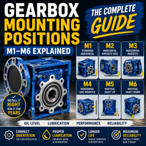
Mounting orientation also affects gearbox lubrication. Read our guide to gearbox mounting positions before specifying a vertical installation.
How to Determine the Axial Load on a Gearbox
The preferred method is to obtain the axial-force data from the driven-equipment manufacturer or calculate it from the machine’s mechanical and process design.
Identify every possible source of thrust
Include process forces, shaft weight, screw action, impellers, helical gearing, coupling restraint and thermal expansion.
Establish the force direction
Use a drawing to show whether the output shaft is pushed towards or pulled away from the gearbox in each operating mode.
Record normal and peak values
Identify steady running thrust, startup thrust, reversing thrust and the highest force expected during blockage or abnormal process conditions.
Identify simultaneous radial loads
Provide pulley, sprocket or external-gear forces together with their distance from the gearbox housing.
Define speed and operating duration
Bearing suitability depends on how fast and how long the shaft rotates while the thrust is applied.
Compare with manufacturer data
Check the exact gearbox size, ratio, output arrangement, mounting position and load direction against the relevant catalogue or engineering calculation.
Simple axial force relationship
Where a known pressure acts across a known effective area, an initial process-force estimate may be obtained using:
This relationship may help with hydraulic pistons, pressure-loaded screws or certain process applications, but it does not replace a full mechanical assessment. Friction, geometry, dynamic loading and material behaviour may also affect the actual shaft thrust.
Force produced by a lead screw
Lead-screw thrust depends on input torque, lead, efficiency and friction. Because real screw efficiency varies with thread design, lubrication and operating direction, use the screw manufacturer’s calculation method rather than relying on a generic efficiency assumption.
A torque-based thrust calculation can produce a dangerously optimistic result if screw efficiency, friction, startup conditions or self-locking behaviour are assumed incorrectly. Use verified machine data wherever possible.
When Is an External Thrust Bearing Required?
An external thrust bearing may be required when the driven machine creates more axial force than the standard gearbox output bearing can safely support.
Typical reasons include:
- High continuous thrust from an extruder or screw
- Large suspended mass on a vertical shaft
- Strong hydraulic or propeller thrust
- Reversing force in both axial directions
- Simultaneous high radial and axial loading
- A long required bearing life under continuous duty
- Process shock or frequent jamming
The external bearing should transfer thrust into a suitable machine frame rather than passing it through the gearbox. However, the shaft arrangement must be designed so that the external bearing and gearbox do not fight each other.
Avoid over-constraining the shaft. Two rigid axial locating systems can create large unintended forces from manufacturing tolerances or thermal expansion. One part of the assembly normally needs controlled axial movement.
Common external arrangements
- Paired angular-contact bearings
- Opposed taper-roller bearings
- A dedicated thrust-bearing housing
- A machine-mounted bearing pedestal
- An extruder thrust-bearing assembly
- A separate shaft supported independently of the gearbox
The design should be completed or verified by a competent mechanical engineer, particularly for high-force, lifting, personnel-safety or critical-process applications.
How to Select a Gearbox for Axial Load
Axial-load selection must be completed alongside torque, speed, service factor, mounting and thermal checks.
Confirm input and output speed
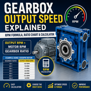
Record motor RPM, gearbox ratio and the actual output-speed range, including VFD operation where applicable.
Calculate required output torque
Establish continuous running torque and any peak torque during starting, blockage, acceleration or reversal.
Apply the correct service factor
Consider operating hours, starts per hour, load type, shock level and the reliability required from the application.
Define axial load in both directions
State normal and maximum push and pull forces, including whether the load reverses with rotation.
Define radial load and force position
Provide any pulley, chain, sprocket or gear force and its distance from the gearbox output face.
Check the exact output arrangement
Solid shafts, hollow bores, shrink discs and flange blocks can have different bearing layouts and load capacities.
Check mounting position and lubrication
Confirm the required orientation, oil quantity, breather arrangement and whether the gearbox operates vertically.
Request a combined-load check
Where meaningful radial and axial forces act together, obtain written approval for the complete load case rather than checking separate headline values.
Information to provide when requesting a gearbox quotation
- Motor power in kW
- Motor input RPM
- Required output RPM
- Continuous output torque
- Peak or starting torque
- Axial load in newtons
- Axial-load direction shown on a sketch
- Whether thrust reverses
- Any radial load in newtons
- Distance of the radial force from the gearbox face
- Operating hours per day
- Starts and reversals per hour
- Mounting position
- Ambient temperature and environment
- Required shaft, bore or flange arrangement
Use our gearbox torque calculator for an initial torque estimate, and our service factor calculator to assess the application’s operating duty.
Worked Gearbox Axial-Load Examples
Example 1: Screw conveyor with continuous thrust
A horizontal screw conveyor requires 900 Nm output torque and produces an estimated continuous axial force of 7,000 N towards the gearbox. The screw may briefly produce 12,000 N during startup with compacted material.
The selection must check:
- Continuous and peak output torque
- 7,000 N continuous inward thrust
- 12,000 N temporary inward thrust
- Operating hours and starts per hour
- Any radial load from the shaft connection
Example 2: Vertical mixer shaft
A vertically mounted gearbox drives a mixer. The shaft and impeller assembly weighs 3,500 N. During operation, the impeller generates an upward process thrust estimated between 1,000 N and 5,000 N.
Possible net axial conditions include:
- 3,500 N downward while stationary
- 2,500 N downward at 1,000 N upward process thrust
- 1,500 N upward at 5,000 N upward process thrust
Example 3: Sprocket plus external helical gear
A gearbox output shaft carries a chain sprocket and an external helical pinion. The sprocket creates radial load, while the helical pinion creates additional radial and axial force components.
The required information includes:
- Chain pull and sprocket pitch diameter
- Sprocket position along the shaft extension
- Helical-gear tangential, radial and axial forces
- Direction of rotation
- Output torque and speed
Example 4: Lead screw producing linear force
A geared motor drives a lead screw used to move a heavy machine slide. The screw converts gearbox torque into a large linear thrust.
Unless the gearbox output bearing is specifically approved for the resulting force, the lead screw should normally use a dedicated thrust-bearing arrangement mounted in the machine frame.
Signs of Excessive Gearbox Axial Load
Possible symptoms include:
- Increasing bearing noise
- Gearbox temperature rising without a clear load increase
- Excessive output-shaft end movement
- Oil leakage at the output seal
- Repeated seal failure
- Metallic particles in the lubricant
- Uneven gear-tooth wear
- Vibration that changes with thrust direction
- Damage to retaining rings or end covers
- Shorter bearing life than expected
These symptoms can also result from misalignment, incorrect lubrication, excessive radial load, contamination or general bearing wear. Stop and isolate the machine safely before inspection.
Our guide to gearbox noise explains common gearbox sounds and potential warning signs.
Common Axial-Load Selection Mistakes
Checking torque but not thrust
Torque capacity does not prove that the gearbox output bearings can support a high axial force.
Assuming both directions are equal
Push and pull capacities may differ because of bearing orientation and internal gear forces.
Ignoring peak thrust
Startup, blockage or process pressure can create a much larger force than normal running conditions.
Checking radial and axial loads separately
Bearings carrying both forces may have less available capacity than each standalone maximum suggests.
Using the gearbox as a thrust block
Standard gearboxes should not automatically be expected to absorb the full force from screws, presses or linear actuators.
Forgetting reversing operation
Reversing a screw, helical gear or process flow can move thrust onto the opposite side of the bearing arrangement.
Over-constraining the shaft
A rigid gearbox bearing and a rigid external thrust bearing can create unintended preload as the system heats and expands.
Providing no force-direction drawing
Words such as inward, outward, positive and negative can be misunderstood without a simple diagram.
How to Reduce Axial Load on a Gearbox
Where the proposed thrust exceeds the standard gearbox capacity, possible solutions include:
- Install a dedicated external thrust bearing
- Support the driven shaft independently from the gearbox
- Select a gearbox with a larger output-bearing arrangement
- Choose a heavy-duty or reinforced-bearing option
- Change the shaft or coupling arrangement
- Reduce process pressure or peak starting load
- Use controlled acceleration and deceleration
- Provide axial movement in the coupling for thermal expansion
- Change the driven component geometry
- Use a purpose-designed extruder, mixer or screw-drive gearbox
Increasing gearbox size may improve bearing capacity, but it is not always the most efficient solution. A correctly positioned external thrust bearing can prevent the process force from entering the gearbox at all.
Axial Load, Service Factor and Gearbox Life
Service factor primarily reflects the application’s duty severity, including operating time, starts and load characteristics. It should not be used as a substitute for a specific axial-load check.
A gearbox with a high torque service factor may still have inadequate output-bearing capacity for the proposed thrust. Equally, a gearbox may support the thrust but have insufficient torque or thermal capacity.
A complete selection checks all of the following:
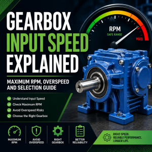
- Input speed
- Output speed and ratio
- Continuous output torque
- Peak output torque
- Application service factor
- Radial load
- Axial load
- Combined bearing load
- Thermal capacity
- Mounting position and lubrication
Read our guides to gearbox service factor and gearbox thermal capacity for further selection guidance.
Frequently Asked Questions
What is axial load on a gearbox?
Axial load is a push or pull force acting parallel to the gearbox shaft centreline. It is also called thrust load or axial force.
What is the difference between axial and radial load?
Axial load acts along the shaft centreline, while radial load acts across the shaft and tries to bend it sideways. Gearbox bearings may need to support both at the same time.
Can a gearbox take axial load?
Most gearbox bearing arrangements can support some axial force, but the permitted value depends on the exact gearbox series, size, ratio, shaft arrangement, speed, direction and simultaneous radial load.
Is thrust load the same as axial load?
Yes. In gearbox and bearing applications, thrust load and axial load normally describe force acting along the shaft centreline.
Does axial-load direction matter?
Yes. A gearbox may have different push and pull capacities because each direction loads different bearing surfaces and may interact differently with internal gear thrust.
Can radial and axial loads act together?
Yes. This is common on shafts carrying sprockets, pulleys or external gears. A combined-load check is required because the separate maximum radial and axial values may not both be available simultaneously.
Do helical gearboxes create axial force?
Helical gear teeth generate an axial component of force because their teeth are angled. The gearbox bearing arrangement is designed to react the internal force, but any additional external thrust must still be checked.
Can a screw conveyor damage gearbox bearings?
Yes. A screw conveyor can create substantial axial thrust, especially during startup, blockage or material compaction. The gearbox or an external thrust-bearing system must be selected for the maximum force.
When should an external thrust bearing be used?
An external thrust bearing should be considered when the machine’s axial force is greater than the gearbox’s permitted external load, where thrust reverses heavily or where a long bearing life is required under continuous high load.
Can service factor compensate for axial load?
No. Service factor helps assess torque-duty severity but does not replace a specific output-bearing and axial-load check.
What information is needed to check gearbox axial load?
Provide the gearbox size and ratio, output speed, torque, axial force, force direction, radial load, force position, operating hours, starts, reversals, mounting position and required bearing life.
What are the signs of excessive axial load?
Possible signs include bearing noise, high temperature, shaft end movement, seal leakage, vibration, abnormal gear wear and premature bearing failure.
Need Help Selecting a Gearbox for Axial Load?
Send us your motor power, output speed, torque, axial force, force direction, mounting position and any simultaneous radial load. Our team can help identify a suitable gearbox range and obtain the required manufacturer load check.