
Gearbox Selection Guide
Gearbox Input Speed Explained: Maximum RPM, Overspeed and Selection
Gearbox input speed is the rotational speed entering a gearbox from an electric motor, engine or other drive source. Selecting a gearbox without checking its permitted input RPM can lead to excessive heat, poor lubrication, seal wear, bearing damage and a shortened operating life. This guide explains how input speed works, how it differs from output speed and what to check before operating a gearbox above or below its normal speed.
Key point: a gearbox ratio determines the relationship between input and output speed, but it does not automatically tell you whether the input shaft can safely operate at a particular RPM. The gearbox manufacturer’s permitted input-speed rating must always be checked separately.
What Is Gearbox Input Speed?
Gearbox input speed is the speed at which the gearbox’s input shaft or motor input rotates. It is normally expressed in revolutions per minute, abbreviated as RPM or min-1.
In a conventional geared motor, the electric motor drives the gearbox input. The motor’s actual shaft speed therefore becomes the gearbox input speed. The gearbox then reduces or, in some specialist arrangements, increases that speed before delivering it through the output shaft.
Drive source
An electric motor, hydraulic motor, engine or other prime mover produces the original rotational speed.
Gearbox input
The rotational speed enters the gearbox through its input shaft, IEC motor flange or coupled input assembly.
Reduced output
The internal gear stages reduce the speed and normally increase the torque available at the output shaft.
A four-pole induction motor operating from a 50 Hz electrical supply commonly runs at approximately 1,400 to 1,480 RPM under normal load. When directly connected to a gearbox, that running speed—not the theoretical synchronous speed—is the approximate gearbox input speed.
Important: the exact running speed of an induction motor varies with motor design and load because of slip. Check the motor nameplate or manufacturer’s data rather than assuming that every four-pole motor runs at exactly the same RPM.
Gearbox Input Speed vs Output Speed
Input speed and output speed describe two different sides of the gearbox:
| Term | Meaning | Usually determined by | Example |
|---|---|---|---|
| Input speed | The rotational speed entering the gearbox | Motor RPM, drive frequency and motor pole count | 1,450 RPM |
| Gear ratio | The reduction between input and output | The internal gear arrangement | 30:1 |
| Output speed | The rotational speed leaving the gearbox | Input speed divided by the gearbox ratio | Approximately 48.3 RPM |
A gearbox may provide the desired output RPM mathematically while still being unsuitable for the proposed input speed. Output-speed calculations and maximum-input-speed checks must therefore be treated as separate parts of gearbox selection.
How to Calculate Gearbox Output Speed
For a conventional reduction gearbox, the basic output-speed calculation is:
Alternatively, where the required output speed and ratio are known, the necessary input speed can be estimated using:
These formulas provide nominal values. Actual speed can differ slightly because the motor slows under load and because variable-frequency drives can alter the electrical frequency supplied to the motor.
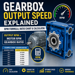
For a quick calculation, use our gear ratio and output speed calculator .
Typical Electric Motor Speeds
The input speed of many industrial gearboxes is determined by the speed of an AC electric motor . Motor speed is principally influenced by the electrical frequency and the number of magnetic poles within the motor.
| Motor pole count | Synchronous speed at 50 Hz | Typical loaded running speed | Common use |
|---|---|---|---|
| 2 pole | 3,000 RPM | Approximately 2,800–2,950 RPM | High-speed pumps, fans and compact drives |
| 4 pole | 1,500 RPM | Approximately 1,400–1,480 RPM | General industrial geared-motor applications |
| 6 pole | 1,000 RPM | Approximately 900–980 RPM | Lower-speed machinery and larger driven loads |
| 8 pole | 750 RPM | Approximately 680–740 RPM | Special low-speed applications |
These figures are general examples rather than guaranteed values. The precise full-load speed should be taken from the motor nameplate or technical datasheet.
Do not select a gearbox solely from the motor’s pole count. A two-pole motor can place significantly greater speed demands on a gearbox than a standard four-pole motor. The manufacturer must permit the proposed input RPM.
What Is Maximum Gearbox Input Speed?
Maximum input speed is the highest input-shaft RPM that the gearbox manufacturer permits under specified operating conditions. It may be shown in a catalogue as:
- Maximum input speed
- Maximum input RPM
- Maximum permissible speed
- Maximum n1
- n1 max
- Input speed limit
The symbol n1 is frequently used for gearbox input speed, while n2 is commonly used for output speed.
There is no single maximum RPM that applies to every gearbox. The permitted speed can vary according to:
- Gearbox type and internal design
- Gearbox frame size
- Gear ratio
- Bearing arrangement
- Lubricant type and viscosity
- Mounting position
- Ambient temperature
- Operating duration
- Applied power and torque
- Whether the duty is continuous or intermittent
Never treat a general online RPM figure as a substitute for the relevant manufacturer’s catalogue. The correct limit must be checked against the exact gearbox series, size, ratio, mounting arrangement and duty.
Why Is Gearbox Input Speed Limited?
Increasing input speed does more than make the output shaft rotate faster. It also increases the number of gear-tooth contacts, bearing rotations and seal movements occurring each minute. This can alter the gearbox’s thermal and lubrication conditions.
Heat generation
Higher rotational speed increases churning, friction and power losses. The gearbox may generate heat faster than its housing can dissipate it.
Bearing speed
Input-shaft bearings have speed, load and lubrication limits. Excessive RPM can increase temperature and reduce bearing life.
Seal wear
Shaft seals experience greater sliding speed at higher RPM. This can accelerate lip wear and raise the risk of lubricant leakage.
Lubricant behaviour
Oil may churn, foam or aerate when internal components rotate too quickly. Lubricant viscosity must also suit the operating speed and temperature.
Gear-mesh velocity
Higher pitch-line velocity can increase noise, vibration and dynamic loading between the gear teeth.
Thermal capacity
Even when the gears can mechanically transmit the required torque, the gearbox may be unable to control the resulting operating temperature continuously.
The relationship between speed and temperature is not always linear. A relatively small increase in input speed can have a meaningful effect where a gearbox is already operating close to its thermal limit.
Read our separate guide to gearbox thermal capacity for more information about heat dissipation and continuous duty.
What Happens When a Gearbox Is Oversped?
Gearbox overspeed occurs when the input or output shaft operates above the speed permitted by the gearbox manufacturer or above the speed for which the complete machine was designed.
Depending on the amount and duration of overspeed, possible consequences include:
- Higher gearbox operating temperature
- Increased gear and bearing noise
- Oil foaming or aeration
- Reduced lubricant film strength
- Accelerated seal wear
- Oil leakage from seals or breathers
- Premature bearing failure
- Increased vibration
- Reduced gearbox service life
- Damage to the driven machine
A gearbox may appear to operate normally during a short overspeed test while still accumulating additional heat or bearing wear. The absence of immediate failure does not prove that the speed is suitable for continuous operation.
Brief overspeed vs continuous overspeed
Some gearbox designs may permit a higher intermittent input speed than their continuous rating. However, this must be explicitly confirmed by the manufacturer. Duration, acceleration rate, load and frequency of occurrence all affect whether a temporary overspeed condition is acceptable.
Loaded vs unloaded overspeed
Operating at high RPM with little load is not necessarily harmless. Bearing speed, lubricant churning and seal surface speed remain relevant even when the output torque is low. Conversely, high speed combined with high transmitted power can create a particularly demanding thermal condition.
How Input-Speed Limits Differ by Gearbox Type
Different gearbox designs respond differently to high input speed. The following comparison explains the general considerations, but the exact manufacturer’s rating remains decisive.
Worm gearboxes
Worm gearboxes use sliding contact between the worm and worm wheel. This produces compact right-angle reduction but can generate more heat than rolling-contact gear designs, particularly at high ratios or demanding duty.
Input speed, ratio, lubricant, ambient temperature and continuous operating time must all be considered carefully.
Inline helical gearboxes
Inline helical gearboxes use meshing helical gears and are often selected for efficient continuous-duty power transmission. Their permitted input speed still depends on gear-mesh, bearings, seals and lubrication.
Helical bevel gearboxes
Helical bevel gearboxes provide efficient right-angle transmission and are widely used on conveyors and process machinery. High input speeds must remain within catalogue limits for the exact size and ratio.
Planetary gearboxes
Planetary units can provide high torque density and may be designed for demanding speed and load conditions. Their input-stage bearings, lubrication system and maximum gear-mesh velocity still impose specific limits.
Selection principle: do not assume that a particular gearbox type is automatically suitable for a certain RPM. Check the exact series and frame-size data, especially when using two-pole motors, high-frequency VFD operation or continuous duty.
Using a Gearbox with a Variable-Frequency Drive
A variable-frequency drive changes motor speed by altering the electrical frequency supplied to the motor. This provides useful speed control but can also cause the gearbox to operate across a much wider RPM range than it would with a direct 50 Hz supply.
When using a gearbox and motor with a VFD, check:
- The motor’s permitted minimum and maximum frequency
- The gearbox’s permitted maximum input speed
- The required output-speed range
- Motor cooling at reduced speed
- Gearbox lubrication at very low speed
- Available motor torque across the speed range
- The machine’s maximum safe operating speed
- Acceleration and deceleration times
Approximate speed relationship
Within the motor’s normal operating region, shaft speed changes broadly in proportion to the drive frequency. A motor running at approximately 1,450 RPM at 50 Hz may therefore run near 1,740 RPM at 60 Hz, although actual speed depends on slip, load and the drive’s control method.
Raising the VFD’s maximum frequency without checking the gearbox can create an overspeed condition. The drive may be capable of producing the frequency, but that does not mean the gearbox, motor, coupling or driven machine is rated for it.
Can a Gearbox Operate Above 50 Hz?
A gearbox may be able to operate above the speed produced at 50 Hz, but approval depends on the specific gearbox and motor combination. Operation above 50 Hz should never be assumed to be acceptable solely because a VFD allows it.
Points that require confirmation include:
- Maximum permitted gearbox input RPM
- Maximum motor mechanical speed
- Motor voltage and torque characteristics above base frequency
- Gearbox thermal capacity at the higher speed
- Maximum output speed of the driven equipment
- Balancing and critical-speed limitations
- Bearing and seal ratings
Above the motor’s base frequency, available torque may fall depending on the electrical supply and drive configuration. A machine can therefore run faster while having less available torque. This must be included in the overall selection.
Can a Gearbox Run at Very Low Input Speed?
Low speed avoids overspeed, but extremely slow operation can create different concerns. Gearboxes often rely on internal gears, bearings or splash mechanisms to distribute lubricant. At very low RPM, oil circulation may become less effective.
Potential low-speed considerations include:
- Reduced splash lubrication
- Insufficient oil reaching upper bearings or gears
- High output torque at low speed
- Motor overheating because its shaft-mounted fan turns slowly
- Repeated starts and stops
- Long periods holding a stationary load
Where a gearbox must operate continuously at very low speed, ask the manufacturer whether the standard lubrication arrangement remains suitable. A forced-lubrication system, different oil level or alternative mounting arrangement may be required in specialist applications.
How to Select a Gearbox for the Correct Input Speed
Use the following process before selecting a gearbox, geared motor or replacement unit.
Identify the drive-source speed
Record the motor’s actual full-load RPM, motor pole count and supply frequency. For VFD applications, identify the complete intended frequency range.
Confirm the required output speed
Determine the normal operating RPM of the driven shaft and any minimum or maximum speeds required during production.
Calculate the required ratio
Divide the input speed by the required output speed. Select the nearest available catalogue ratio and calculate the resulting actual output RPM.
Check maximum permitted input speed
Compare the highest possible motor RPM against the input-speed limit for the exact gearbox series, size and ratio.
Check torque and service factor
Confirm that the gearbox can transmit the required continuous and peak torque, including shock loads, starts per hour and operating duration.
Check thermal capacity
Ensure the gearbox can dissipate the heat generated by the proposed input speed, power, duty cycle, mounting position and ambient temperature.
Confirm lubrication and mounting position
Check oil quantity, lubricant grade, breather position and mounting arrangement. These can affect whether a given speed and duty are acceptable.
Verify the complete machine
Confirm that couplings, belts, chains, shafts, guards and the driven equipment are also suitable for the maximum proposed speed.
Information to provide when requesting a gearbox quotation
- Motor power in kW
- Motor full-load RPM
- Motor frame and flange size
- Required gearbox output RPM
- Required output torque
- Operating hours per day
- Starts per hour
- Shock or load characteristics
- Mounting position
- Ambient temperature
- VFD minimum and maximum frequency
- Required output-shaft or hollow-bore size
Worked Gearbox Input-Speed Examples
Example 1: Four-pole motor with a 30:1 gearbox
A four-pole motor has a full-load speed of 1,450 RPM. It is connected to a gearbox with a nominal ratio of 30:1.
Calculation: 1,450 ÷ 30 = 48.3 RPM
Example 2: Two-pole motor replacing a four-pole motor
An existing gearbox was originally driven by a 1,450 RPM four-pole motor. A 2,900 RPM two-pole motor is proposed as a replacement while the gearbox ratio remains unchanged.
The gearbox input speed would almost double, and the output speed would also almost double. Heat generation, bearing speed and seal surface speed may rise significantly.
Example 3: Increasing VFD frequency from 50 Hz to 70 Hz
A motor runs at approximately 1,450 RPM at 50 Hz. The VFD maximum frequency is increased to 70 Hz.
Estimated speed: 1,450 × 70 ÷ 50 = 2,030 RPM
Example 4: Selecting a ratio for 25 RPM output
A motor runs at 1,440 RPM and the machine requires approximately 25 RPM.
Required ratio: 1,440 ÷ 25 = 57.6
A standard ratio close to this figure would be selected, followed by checks for actual output speed, torque capacity, service factor, thermal capacity and maximum input speed.
Common Gearbox Input-Speed Selection Mistakes
Assuming all motors run at 1,500 RPM
A 1,500 RPM figure is the synchronous speed of a four-pole motor at 50 Hz. The actual loaded speed is normally lower and varies by motor.
Using ratio alone
A ratio may produce the required output RPM while the gearbox remains unsuitable for the input speed, power, torque or thermal duty.
Replacing a four-pole motor with a two-pole motor
This can almost double gearbox input and output speed unless the ratio or VFD settings are changed.
Increasing VFD frequency without checks
A higher frequency can push the gearbox, motor and machine above their rated mechanical speeds.
Ignoring low-speed lubrication
Very slow continuous operation may reduce lubricant circulation even though the gearbox is well below its maximum RPM.
Ignoring mounting position
Mounting position affects oil level and lubrication. A speed approved in one configuration may require different oil arrangements in another.
Checking only the gearbox
The coupling, driven shaft, pulley, chain, guard and machine may have lower speed limits than the gearbox itself.
Assuming intermittent duty removes all limits
Short operating periods can reduce heat accumulation, but bearings, seals and rotating components still have mechanical speed limits.
Signs That a Gearbox May Be Running Too Fast
Possible warning signs include:
- A sudden increase in gearbox temperature
- Higher-pitched whining or unusual mechanical noise
- Oil foaming visible through a sight glass
- Oil escaping through a breather
- New shaft-seal leakage
- Increased vibration
- Rapid lubricant discolouration
- Bearing noise after operation
- A burning-oil smell
These symptoms can have causes other than overspeed, including misalignment, incorrect oil level, worn bearings or excessive load. Stop the machine safely and investigate the complete operating condition rather than assuming a single cause.
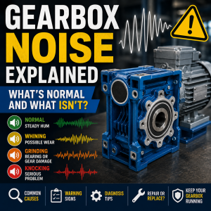
Our guide to gearbox noise explains how to distinguish common operating sounds from potential warning signs.
Input Speed, Torque and Power
Speed cannot be considered in isolation. Gearbox selection must account for the relationship between input power, rotational speed and torque.
For the same transmitted power, reducing rotational speed increases torque. Conversely, increasing rotational speed reduces the torque associated with a given power level. Gearbox efficiency and service conditions must also be included.
Use our gearbox torque calculator to estimate torque from motor power, speed, ratio and efficiency.
The calculated torque must be checked against the gearbox’s rated output torque and adjusted for the application’s service factor, shock loading, starts per hour and operating duration.
How Mounting Position Affects High-Speed Operation
Gearbox mounting position controls where oil collects inside the housing and which bearings or gear stages are immersed or splash-lubricated.
A vertically mounted gearbox may require a different oil quantity, breather location or lubrication arrangement from the same unit installed horizontally. At elevated input speeds, incorrect oil level can increase churning losses, temperature or lubrication risk.
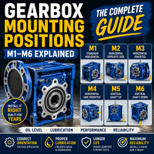
Always state the required mounting position when requesting a gearbox. Read our complete guide to gearbox mounting positions for further information.
Frequently Asked Questions
What is gearbox input speed?
Gearbox input speed is the rotational speed entering the gearbox through its input shaft or motor connection. It is normally measured in RPM and is frequently shown as n1 in technical catalogues.
What is the maximum input RPM of a gearbox?
There is no universal maximum input RPM. The permitted speed depends on gearbox type, series, size, ratio, bearings, lubrication, mounting position, power and duty. Check the manufacturer’s data for the exact gearbox.
Can I use a 2,800 RPM motor with a gearbox?
Only where the specific gearbox is rated for the motor’s actual input speed, power and duty. A two-pole motor generally runs much faster than the four-pole motors commonly used with industrial gearboxes.
What happens if a gearbox runs above its rated speed?
Overspeed can increase heat, bearing speed, seal wear, gear noise and lubricant churning. It may reduce gearbox life or cause premature failure, particularly during continuous high-load operation.
How do I calculate gearbox output speed?
Divide the gearbox input RPM by the gear ratio. For example, 1,450 RPM divided by a 30:1 ratio gives an estimated output speed of approximately 48.3 RPM.
Does increasing VFD frequency increase gearbox speed?
Yes. Increasing the drive frequency generally increases motor and gearbox input speed. The maximum frequency should be limited so the gearbox, motor and driven machine remain within their permitted mechanical speeds.
Can a gearbox run continuously above 50 Hz?
It may be possible, but it requires confirmation from the gearbox and motor data. Maximum input RPM, motor torque above base frequency, thermal capacity and machine speed limits must all be checked.
Can running a gearbox too slowly cause problems?
Yes. Very low continuous speeds can reduce splash lubrication and can cause motor cooling problems because the motor fan also turns more slowly. Specialist advice may be needed for extreme low-speed operation.
Is input speed the same as motor speed?
It is the same where the motor is directly connected to the gearbox. If belts, pulleys, chains or an additional reduction stage are fitted between them, the gearbox input speed may differ from the motor shaft speed.
Does a higher gearbox input speed increase the output speed?
Yes. With the ratio unchanged, output speed rises in proportion to input speed. If input speed increases by 20%, nominal output speed also increases by approximately 20%.
Need Help Selecting a Gearbox?
Send us your motor power, motor RPM, required output speed, output torque, mounting position and operating duty. We can help identify a suitable gearbox ratio and check the proposed input speed against the selected range.